Vias: Au or Cu Solid Filled

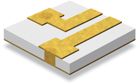
Au Solid Filled Via

Au Solid Filled Vias

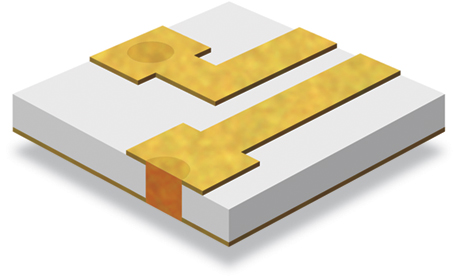
  Cu Solid Filled Via

Cu Solid Filled Vias

Au or Cu Solid Filled Vias


Electrical Current Limits For Solid-Filled Vias

Introduction

How much DC current can safely be passed through a Copper-filled via? To answer this question, we must specify how the Joule heat generated in the via will escape. Usually, the B-face of a thin-film circuit is brazed or epoxied to a metal package base or carrier. The exposed A-face has thin-film traces and other circuit elements on it.

Joule heat generated in the Cu-filled via exits through the package base. This is the model we will analyze. Details of the mathematical analysis are deferred to the Appendix.

Thermal Model
Thermal Model

The figure at right shows a cross-sectional view of the assembly to be analyzed. The ceramic substrate with an isolated Cu via is brazed to a Tungsten:Copper (W:Cu) carrier. The carrier is firmly mounted to a system heatsink whose temperature is Ta.

Copper has such a high thermal conductivity that for this analysis, heat leaks from the via’s upper surface and through the via walls can be neglected. Essentially all of the Joule heat will exit through the via’s lower end and thence through the carrier to the system heatsink. We’ll return to this assumption in Summary And Conclusions.

For our model, the via’s upper end is the hottest point, with a temperature, Tm. Most circuit designers would not want Tm to be much above 100°C so this will be our design limit. An expression in the Appendix enables other choices for Tm to be made.

The system heatsink temperature, Ta, often is specified to be 80°C.

Numerical Parameters
Material Parameter Symbol Value Units
Cu Electrical
Resistivity
ρ 2.8 × 10⁻⁸ Ohm-meters
Thermal
Conductivity
κ 391 Watts/meter Kelvin
W:Cu, (80:20) Electrical
Resistivity
ρ1 5.0 × 10⁻⁸ Ohm-meters
Thermal
Conductivity
κ1 248 Watts/meter Kelvin
Via Dimensions
Height (H) 0.38mm (0.015")
Diameter (D) 0.28mm (0.011")
Results
Tm (°C) Im (Amperes) Pm (Watts) Rvia (Ohms)
100 88 1.325 1.7 × 10⁻⁴
Summary And Conclusions

An extremely large DC current (88 Amperes in this exampe) is required to heat the via’s A-face to 100°C

The present analysis has ignored the problem of passing such a large current into and out of the via.

Standard thin-film Au traces could not safely sustain such a high current.

An Au or Cu via is safe to operate with any electrical current that the thin-film circuit traces can safely deliver to it.

Some Joule heat will escape through the via walls into the ceramic substrate and down to the system heatsink. Thus Im given above is a lower bound for the current that will bring the via’s A-face up to 100°C.

Cross section of Au Solid Filled Via

Cross section of Au Solid Filled Via

 
Cross section of Cu Solid Filled Via

Cross section of Cu Solid Filled Via

 
Au or Cu Solid Filled Via

The Au or Cu Via is completely filled and planarized, which provides a low inductance ground path on both sides without the need for venting structures, dissimilar metals or exposed oxides. Filled vias can also act as a thermal pathway for two-sided signal interconnects. ATP offers three types of solid filled via circuits: Au, Cu and Polyimide. Filled vias are available on Alumina (Al2O3), Aluminum Nitride (AlN) and Beryllium Oxide (BeO).

Au/Cu Solid Filled Via sizes
Substrate
Thickness
Ideal Via Diameter Minimum Via Spacing
Center to Center Center to Edge
0.010"
(0.254mm)
0.007"–0.0010"
(0.177–0.254mm)
0.014"–0.020"
(0.356–0.508mm)
0.008"–0.009"
(0.203–0.229mm)

0.015"
(0.381mm)

0.011"–0.015"
(0.279–0.381mm)
0.022"–0.030"
(0.558–0.762mm)
0.010"–0.012"
(0.254–0.305mm)

0.020"
(0.508mm)

0.015"–0.020"
(0.381–0.508mm)
0.042"–0.060"
(1.066–1.524mm)
0.012"–0.014"
(0.305–0.356mm)
0.025"
(0.635mm)
0.017"–0.020"
(0.431–0.508mm)
0.051"–0.060"
(1.295–1.524mm)
0.013"–0.014"
(0.330–0.356mm)
0.030"
(0.762mm)
0.020"–0.025"
(0.508–0.635mm)
0.060"–0.075"
(1.524–1.905mm)
0.014"–0.017"
(0.356–0.432mm)
Filled Via Planarity
Front Side +0/-0.001"(+0/-0.0254mm)
Back Side +0.0002"/-0.001"(+0.00508/-0.0254mm)
 

Mathematical Appendix


Consider only the Joule heating in the Cu-filled via and its spreading through the package base to the system heatsink. Then the current, Im, required to heat the via’s A-face to a temperature, Tm, is given by the following expression:

Im = (π/4)(D2/H) { 2(Tm – Ta)(κ/ρ) } ½
[1 + (π/4))(κ/κ1)(D/H)]

Where D and H are the via’s diameter and height respectively, ρ and κ are the via metal’s electrical resistivity and thermal conductivity respectively,
κ1 is the thermal conductivity of the package base metal,
Ta is the temperature of the system heatsink.

If we assume that the current, Im, spreads from the via’s B-face into the W:Cu base and to the system heatsink, then we can estimate the heating from this source. The spreading resistance from a circular source of diameter, D, is given by:

Rsp = ρ1/(2D)

where ρ1 is the electrical resistivity of the W:Cubase.

For the present problem, Rsp = 0.89 × 10⁻⁴ Ohms compared with the via’s resistance of 1.73 × 10⁻⁴ Ohms. The additional heating from the W:Cu will reduce the value of Im from 88 to 86 Amperes. The preceding conclusions remain valid.


Company Technologies Capabilities Design Guidelines Products Other

Introduction

Polyimide Bridges

Photomasks

Standard Dimensions, Tolerances

Inductor Coils

Home

Quality Assurance

Solder Dams

Substrates

CAD Data Guidelines

Inductor Coils Eng. Kit

Contact Us

Directions

Laser Diode Submounts

Material Specifications

Material and Conversion Tables

Microstrip Transmission Lines

Careers

Careers

Vias: Plated Through

Ion Beam

Thermal Performance

Transmission Lines Eng. Kits

Terms of Use

Sales Rep’s

Vias: Au or Cu Solid Filled

Aluminum Bonding Pads

Aging Equation

Stand Off/Isolation Pads

Privacy Policy

Contact Us

Edge Wraps

Laser Machining/Drilling

Safe Current Limits

ATP Bond Qualification Coupons

Facebook


Gold Bumping

Backside Burnishing

Design Resources

Product Samples

YouTube


Fractal Fasten

Standard Metallizations


Packaging/Chip Trays


Integrated TaN Resistors


Thin Film Resistor and Multi-Tap


Laser Resistor Trimming


Serialization