Tantalum Nitride Resistor Aging Equation
Definitions
T(°K) = T(°C) + 273.15
Aging Equation
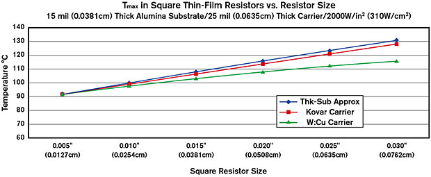
Thermal PerformanceThe Thermal Performance page discusses the calculation of a resistor’s operating temperature. Figure 3 shows Tmax for square resistors operating with 2,000 W/in2 (310 W/cm2) and 85°C heatsink temperature.
ExampleThe 5 mil (0.127 mm) square resistor in Figure 3 has P = 50 mW and Tmax = 92.2 °C. Assume MTTF = 1 × 10⁸ hours. How much will the value of the resistor increase in 108 hours of operation with 50 mW of dissipation? From the Aging Equation: ΔR/Ro = 0.13%, is this increase in resistance acceptable? A sensitivity analysis of the circuit’s operation must be done to answer that question. ReferenceBrady, et.al., Thermal Oxidation and Resistivity of Tantalum Nitride Films, Thin Solid Films 66 (1980), pp. 287–302. |

Figure 3 |
|||||||||||||||||||||||||||||||||
Resistor Stabilization
|
||||||||||||||||||||||||||||||||||
| TCR | = | (R2 – R1) | × 106ppm/°C |
| R1(T2 – T1) |
| Where: | ||
| R2 | = | final resistance (Ω) |
| R1 | = | initial resistance (Ω) |
| T2 | = | final temperature (°C) |
| T1 | = | initial temperature (°C) |
Example: 50 Ohm resistor at 25°C which drifts to 49.5 Q at 125°C has a TCR of:
| TCR | = | (49.5 – 50) | × 106 = –100ppm/°C |
| 50(125 – 25) |
The TCR of Tantalum-Nitride is typically measured within a range from –25 to –150 ppm/°C.
Reference
MIL-PRF-38534H Appendix C.3.7.5.3.1 b
Power Dissipation
Resistor film temperature is the critical parameter in determining the failure point of a resistor. This operating temperature is affected by resistor geometry, total circuit power dissipation, proximity to other dissipative elements, type of substrate material and the heatsinking used. A complete thermal analysis is required to precisely determine the resistor temperature Tmax. The maximum allowable power dissipation for the circuit’s critical resistor depends on the system’s design lifetime (MTTF), the maximum acceptable increase in resistance over the system’s lifetime and other factors that might affect the critical resistor’s operating temperature such as duty cycle and average heatsink temperature. Typical CW applications indicate a resistor temperature in the 100°C to 125°C range.
Note that for every 10°C rise in resistor temperature over 100°C, resistor stability degrades by a factor of 2.8 in oxygen and does not apply to resistors in sealed nitrogen environments. Specifically, a resistor value which drifts by 0.5% at 100°C will drift as much as 1.4% if operated at 110°C. An important point to be made, however, is that this value applies in an air environment because of continued oxide growth into the resistor film.
Please request document #DG50020 “Design For Manufacturability,” in PDF format (requires Adobe Reader).

